
Manual trigger with arcade button for eurorack
I wanted to create my own module for eurorack from start to finish and make my first pcb layout. This is my journey to my diy arcade trigger eurorack module.
Table of Contents
What I wanted to build
I wanted a really simple module as a start, as I am not experienced in circuit design nor pcb layout. I decided the following things were important to me:
- two manual triggers with inverted outputs
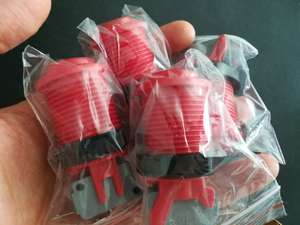
- Arcade buttons as triggers as they are easy to get, look nice and feel awesome
- an awesome graphic on the front with my domain
- gerber files at the end so everybody who wants, can order the boards
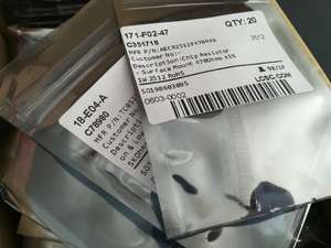
- all parts should be able to be ordered from LCSC so everybody can order them for reasonable priced (and i wanted to try it by myself)
- SMD for everything to keep the front panel clean and just try it and learn to solder the small parts
Circuit design and simulation
I designed the circuit in an online circuit simulator where I could see problems easy. My design can be found here: http://www.falstad.com/
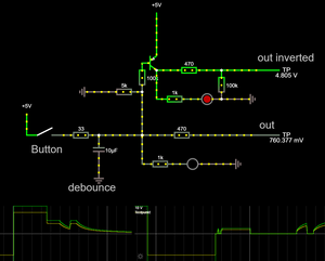
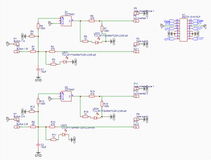
After everything worked, I copied the schematic into in easyeda project.
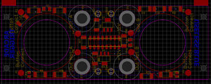
PCB layout
The pcb layout was pretty straight forward. I positioned the cutouts for the buttons, the leds and jacks and just scattered the rest of the parts in the remaining spaced and let the auto router do its magic.
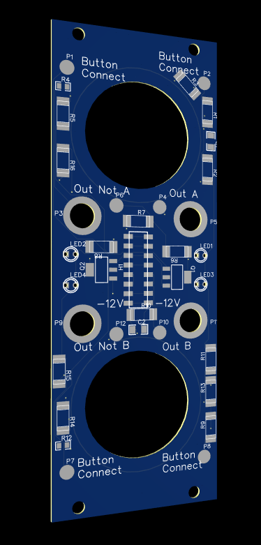
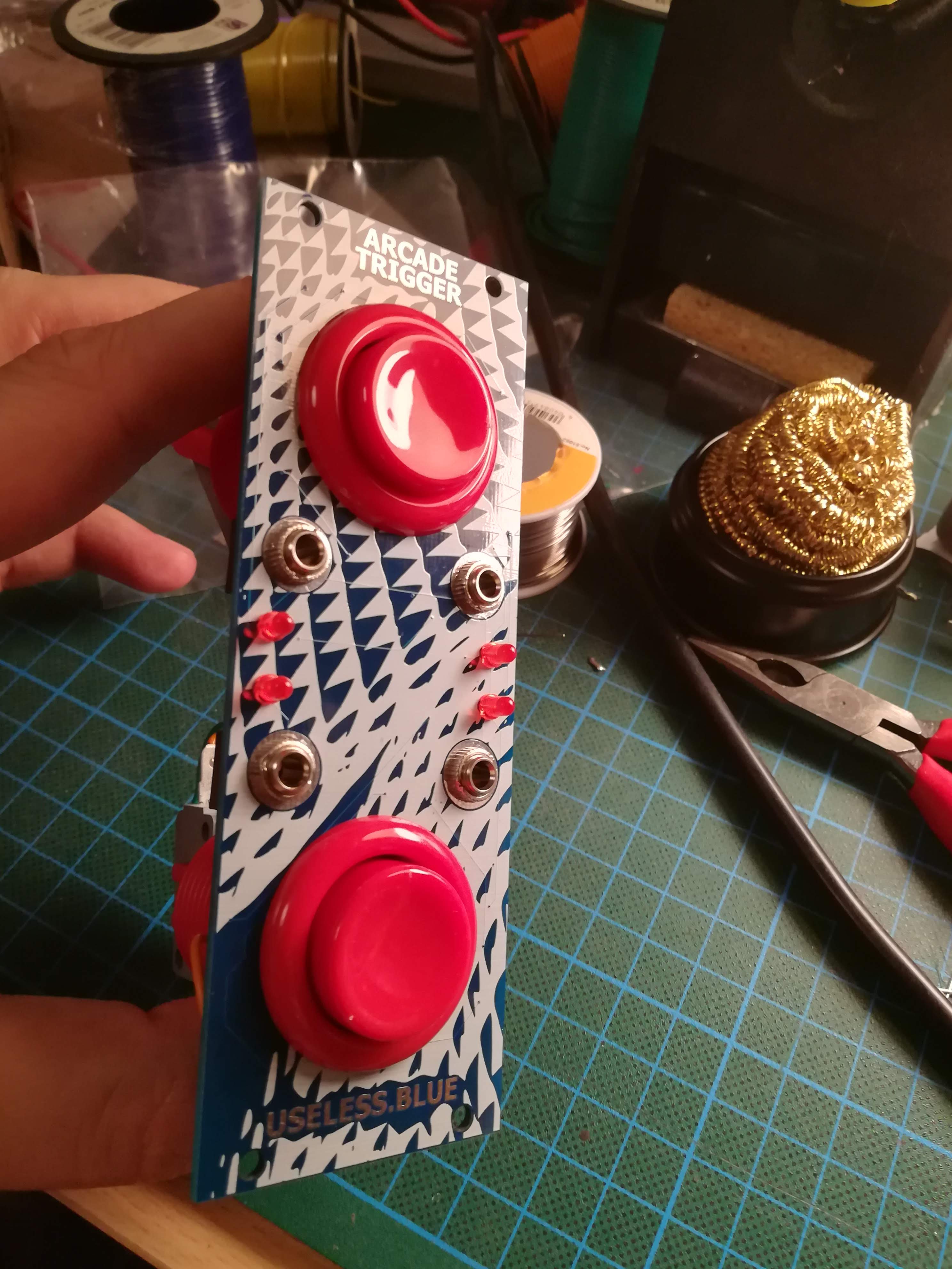
Frontpanel design
I wanted a nice looking front panel design. I exported the pcb as pdf, loaded it in photoshop. A nice image from unsplash with a cool pattern was then put over it to see if the graphic fits. Tis image was then exported and imported in easyeda to the silkscreen layer.

I left the space blank where the module name and my domain should be placed. I used the text tool in easyeda to place the text on the copper layer and also removed the soldermask at the same place.

Design files/Download
All design files are on github and free for you to use. https://github.com/DerGrosseDaniel/Eurorack-manual-trigger-arcade-button/ You can find the gerber filed there, schematics, BOM, easyeda project and Altium files.
You can also find the project on easyeda and generate the LCSC shopping cart here: https://easyeda.com/editor#id=|0693ec3244404dddbe72cb1ff47d0b71|332907a0c0794c048bfa6cc9fd1ebf4f
PCB and part order
I ordered the pcbs on jlcpcb, but any place will be fine. I got 1.6mm thick pcbs but I would strongly suggest 2mm for more rigidity.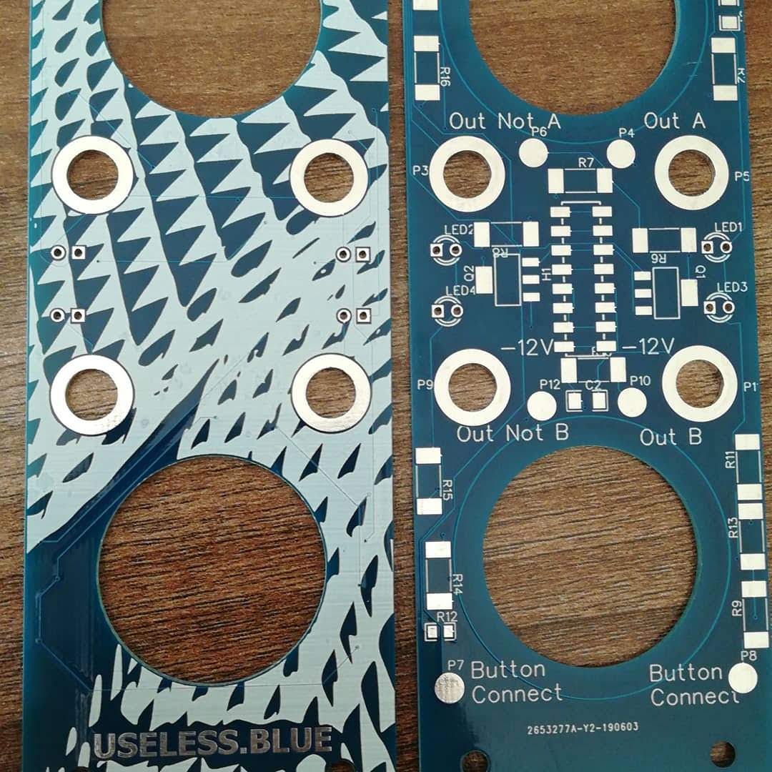

For the arcade buttons I ordered 6 on ebay for another project. You can get whatever you want as long as they fit into the holes of the pcb.
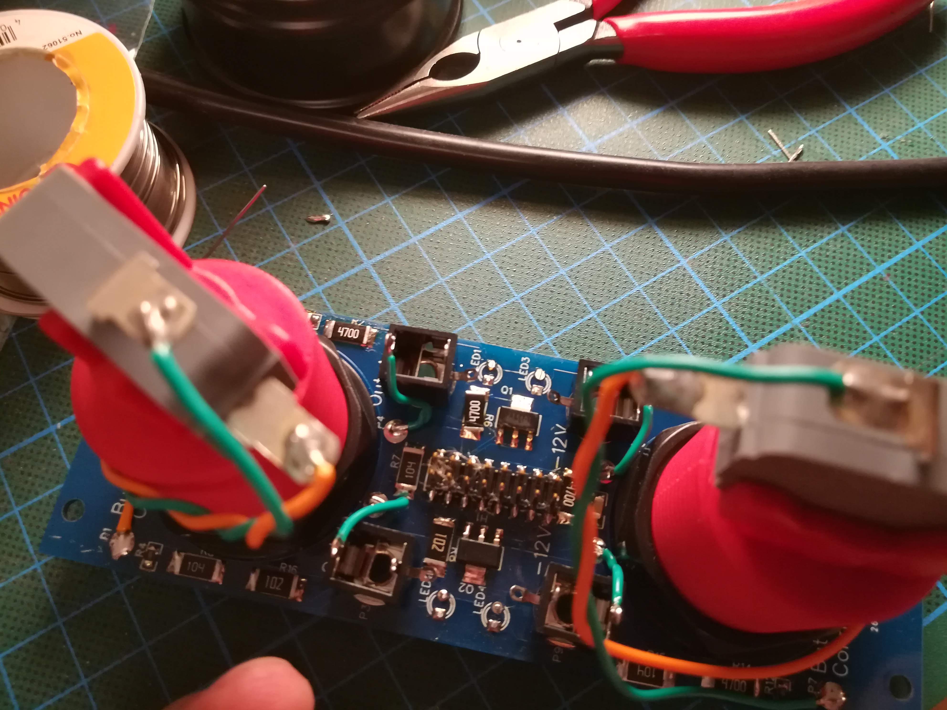
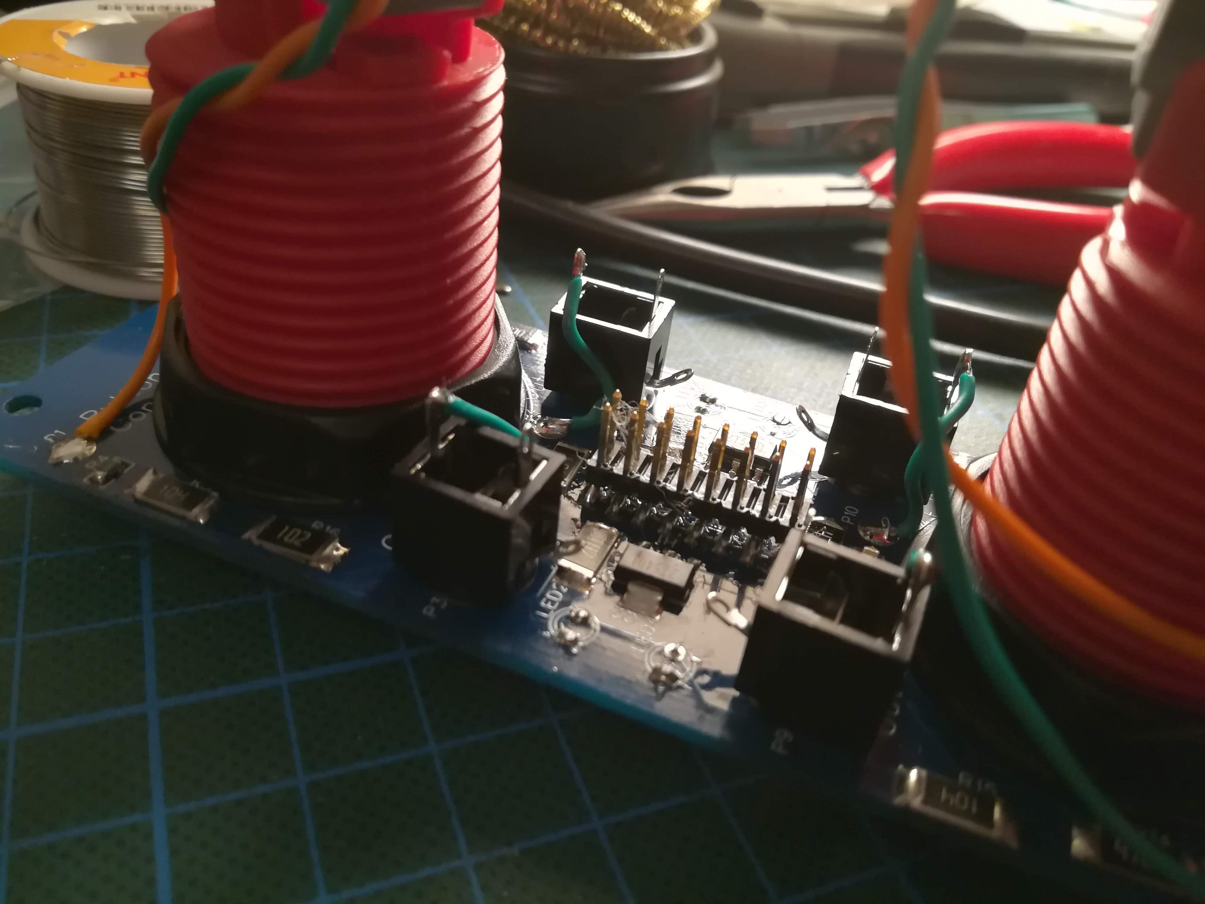
Soldering
I started from the inside out and soldered all components. It works, but didn't look that professional. But lots of flux helps.

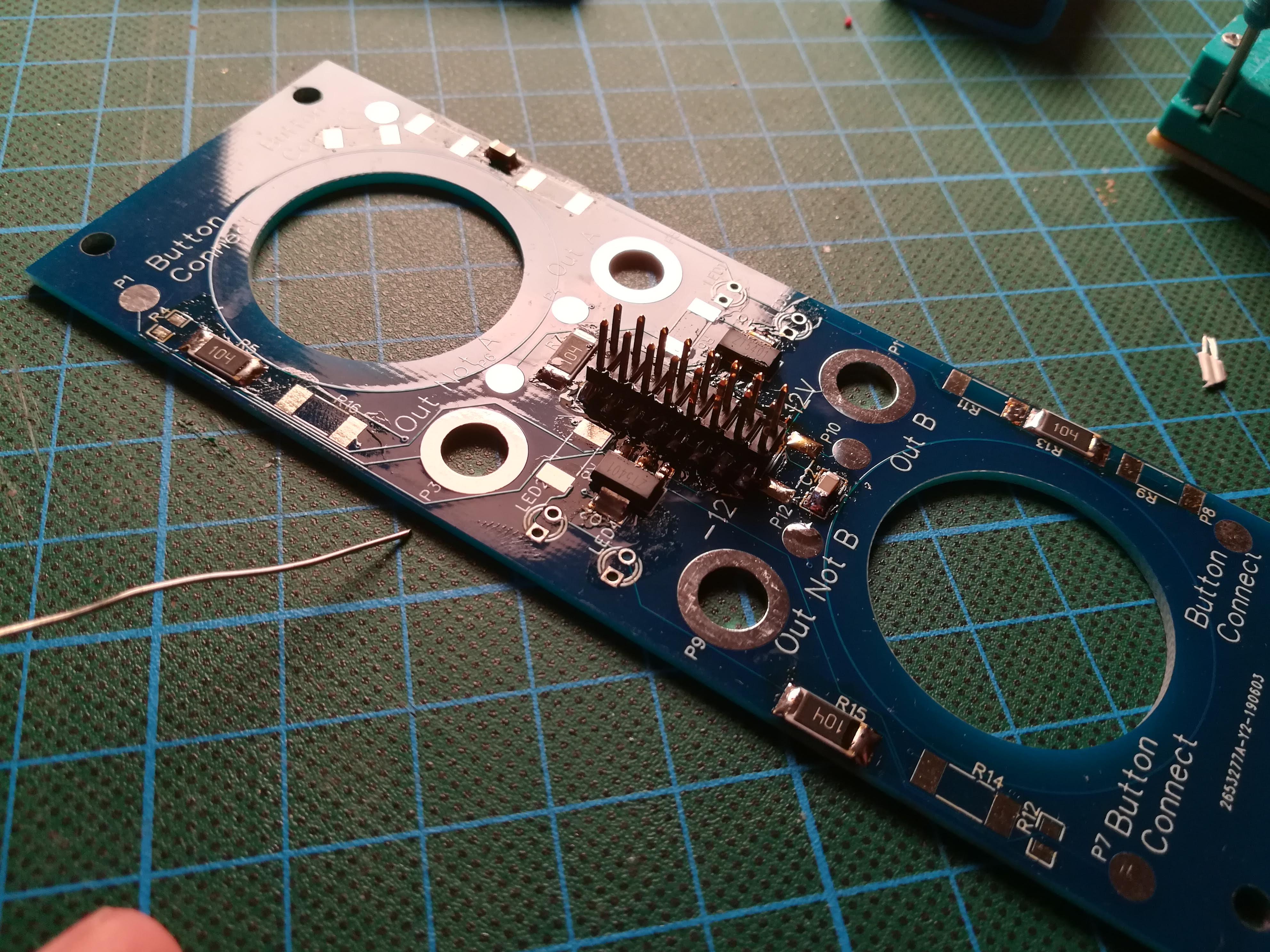
After I soldered all SMD components I installed the LED and the jacks. The tip was connected with a short wire to the round pad next to it and the sleeve is grounded via the nut and the front plate. The arcade buttons followed last. The wires to the button are soldered to the pads next to it (polarity is not relevant).

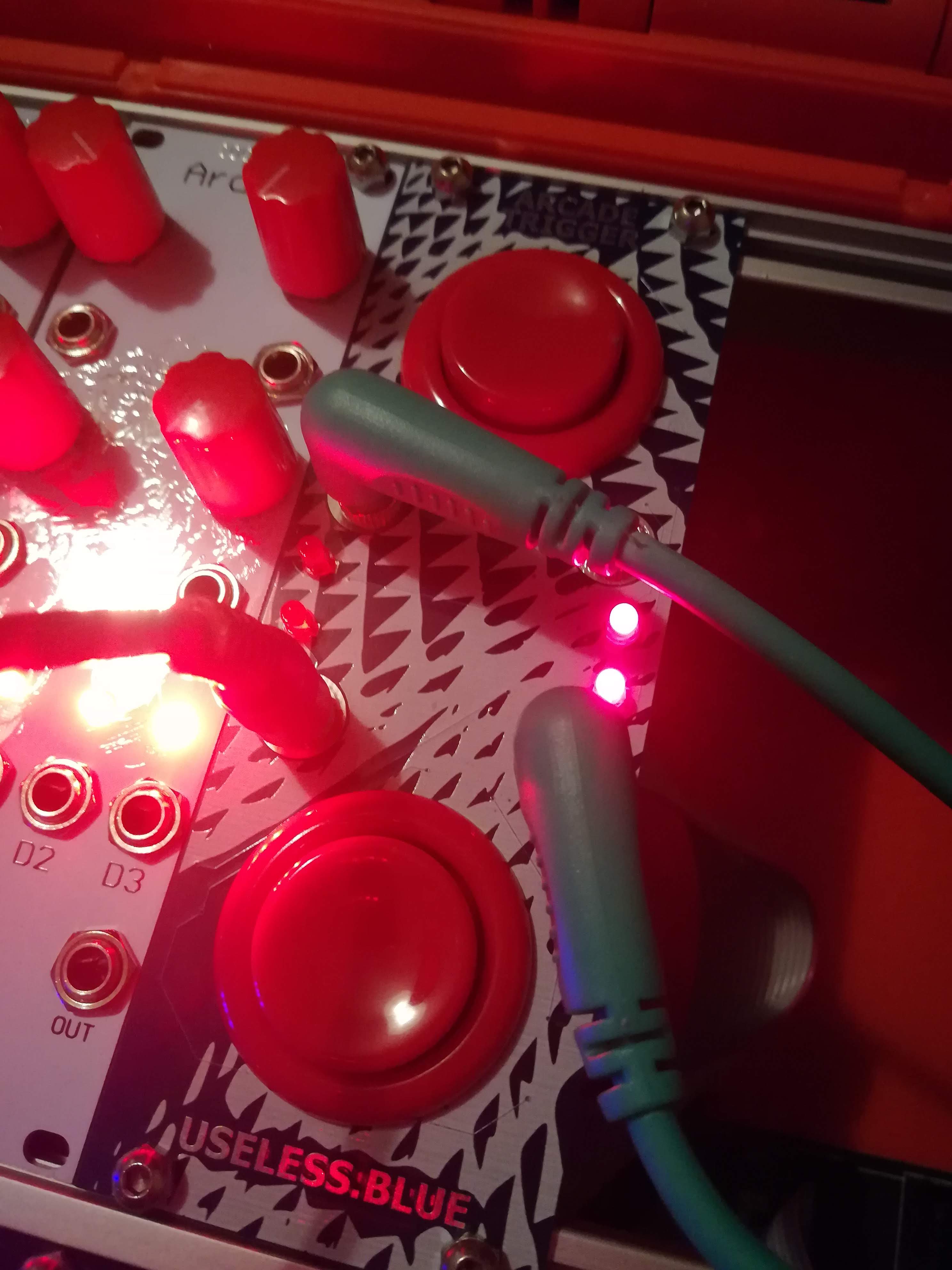
Result
Everything worked and my first designed module was a success.
What would I change
Everything worked out, but there aspects where my choices weren't perfect.
- I should choose a thicker pcb for the front panel. It is flexing too much when I insert a cable
- The bigger smd parts are too big. 2512 are way too big, 1206 are fine and even 0805 are OK, even when they are not that easy. But the 2512 use way to munch space.
- Everything on one board was neat, but a two board construction with a dedicated front panel would be a nicer choice. Flex wouldn't be such an issue and the i could use through hole components without disturbing my art on the front.
- Ordering with LCSC went fine, but the goal to make an easy shareable card failed. Mouser will be my next choice.