Eurorack stomp box tuner
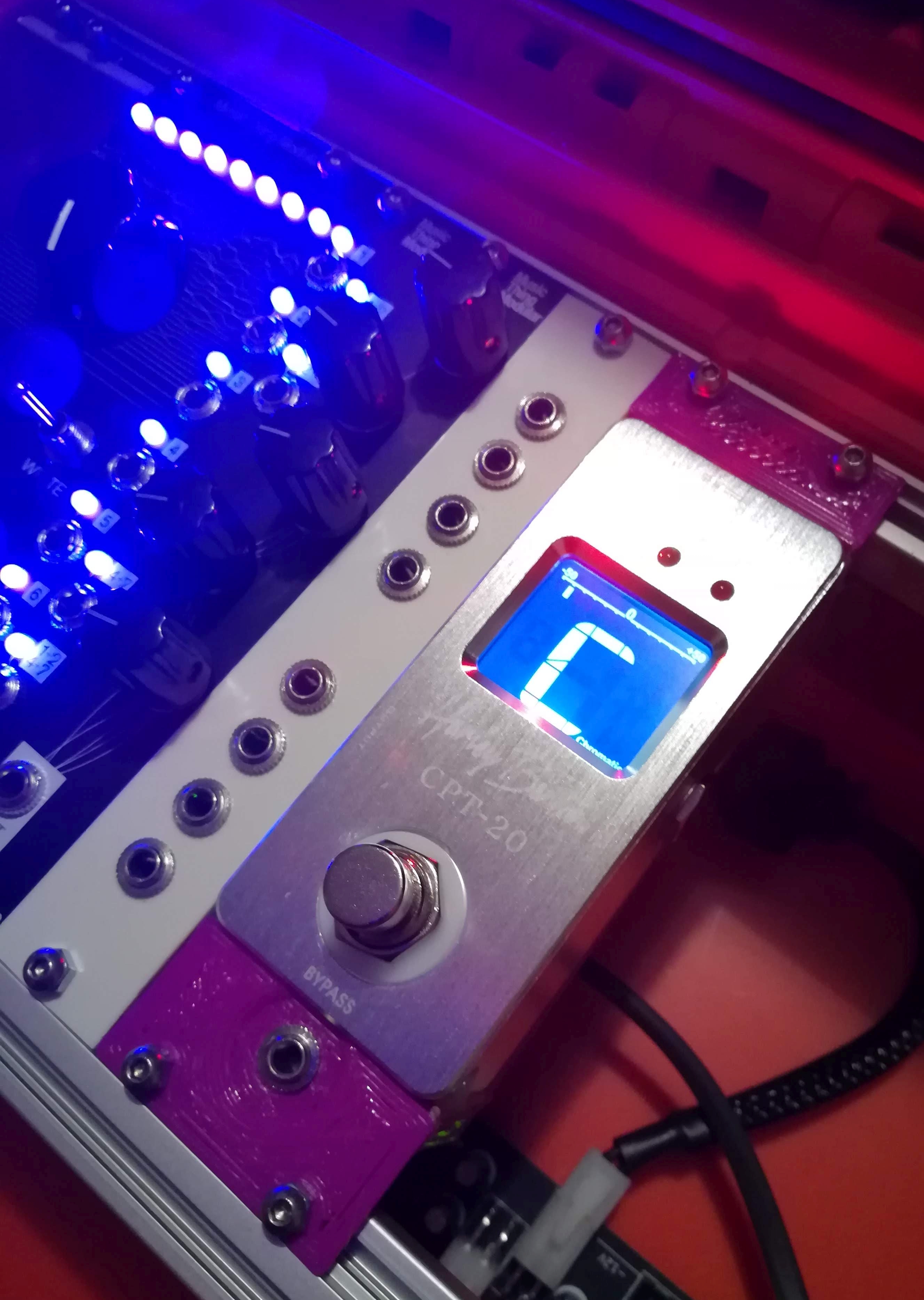
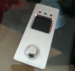
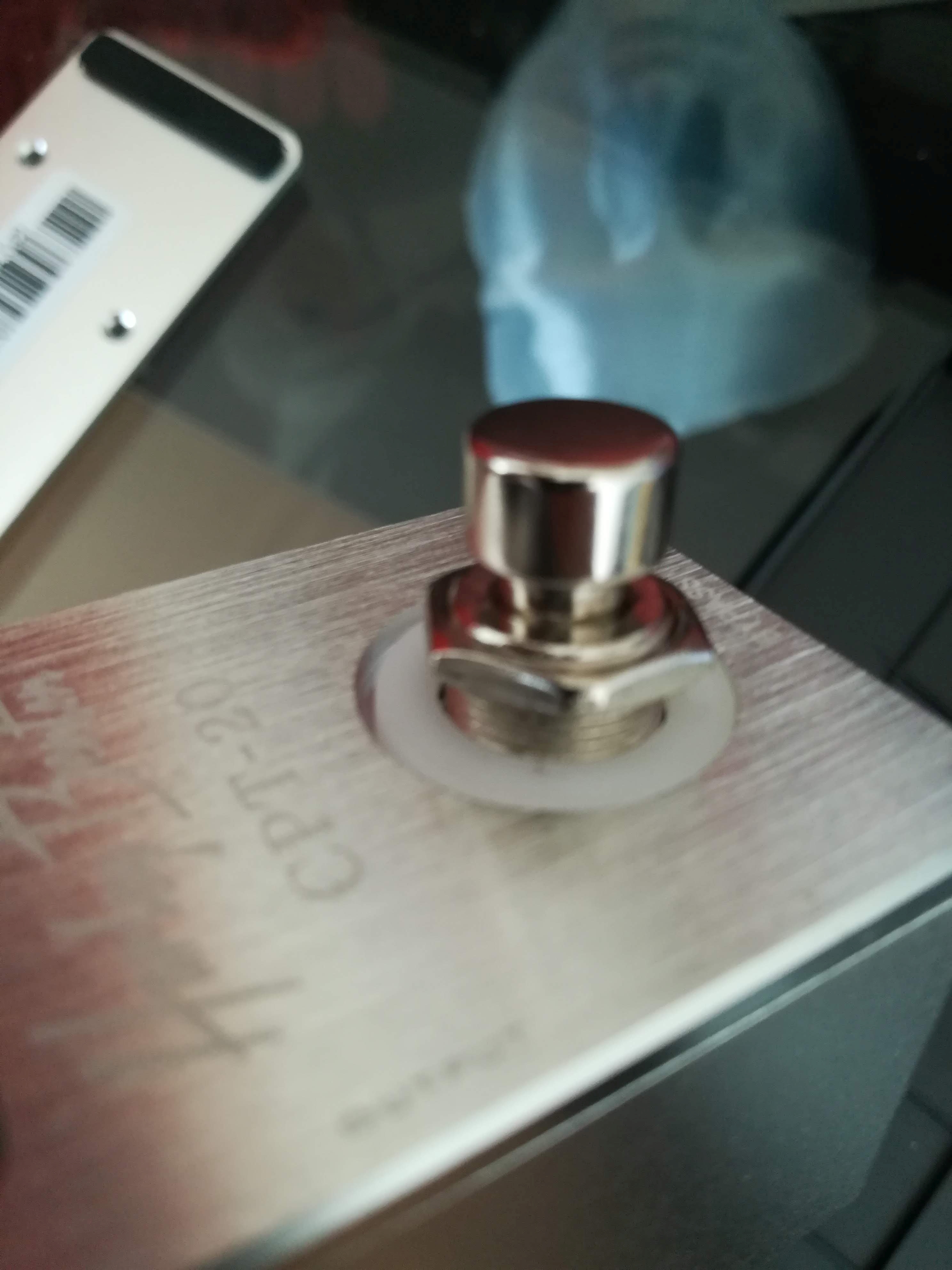
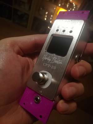
I've got the idea that a tuner for my modular synthesizer would be nice. And the cheapest route in my mind would be to convert a guitar pedal tuner. So I bought the cheapest one I could get. When the glorious Harley Benton CPT-20 arrived at my home, the journey began...
Table of Contents
Disassembly
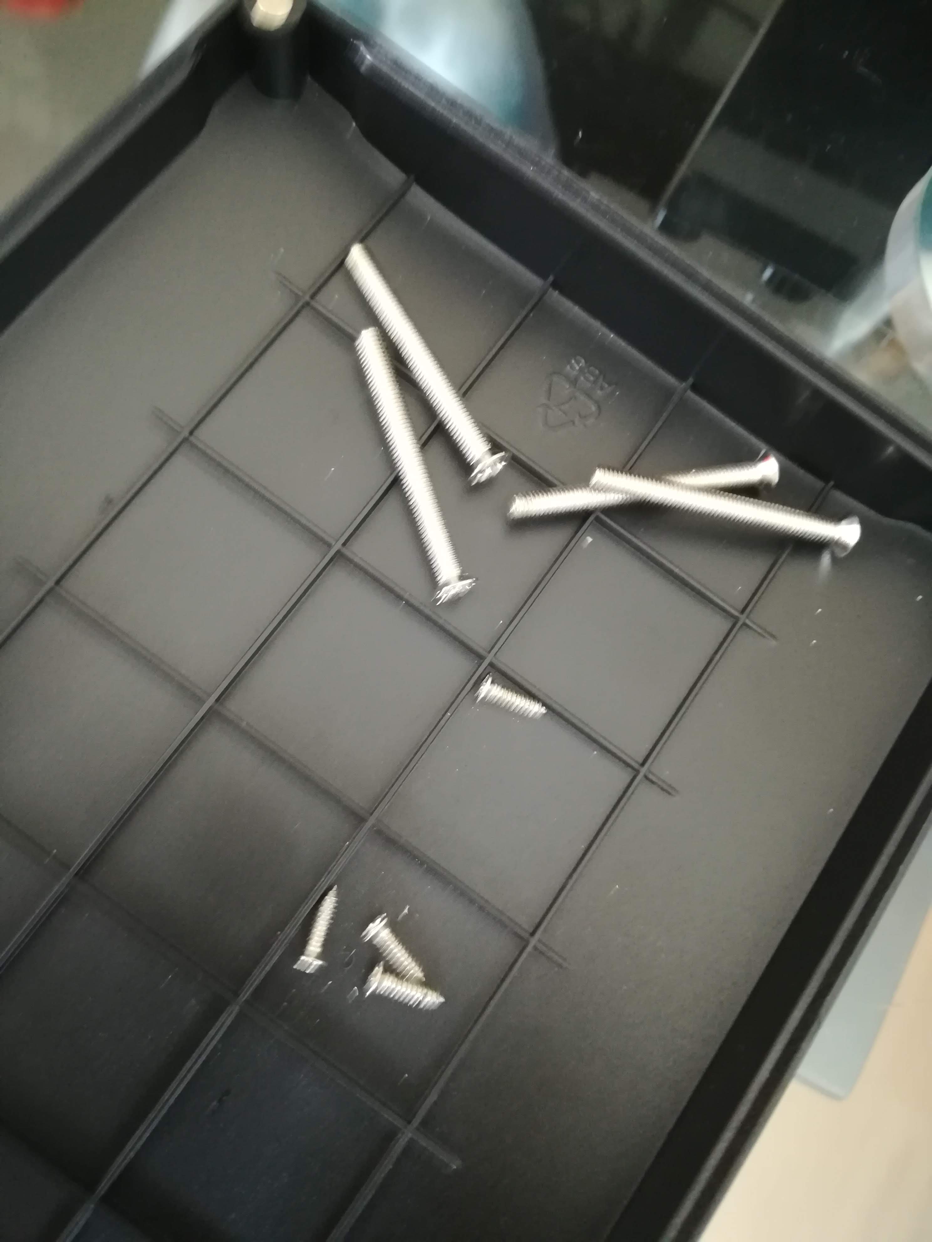
"Don't turn it on, take it apart!" That was my plan. I removed four screws on the bottom, then another four screws beneath the rubber feeds.

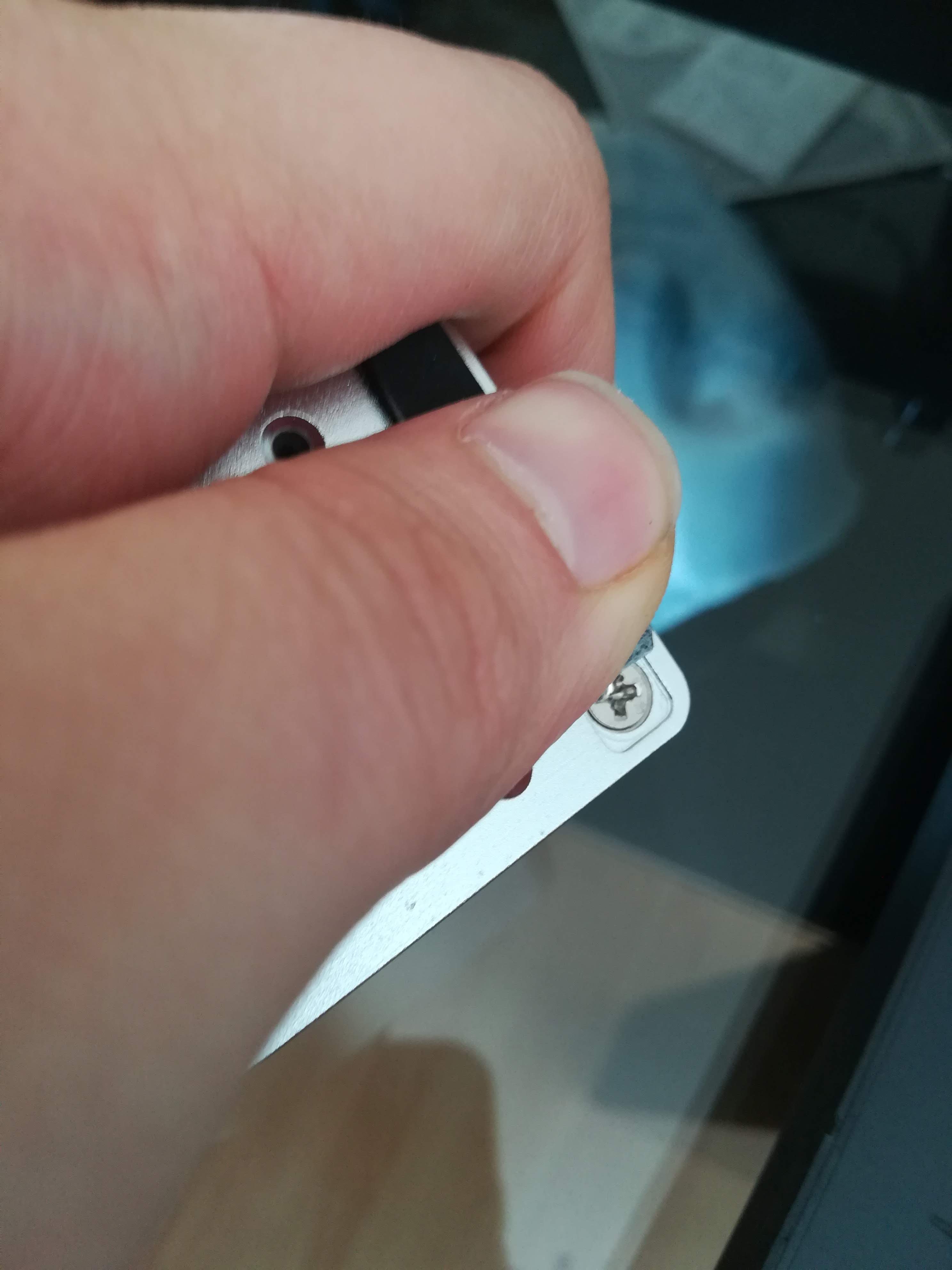
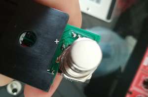
I wanted to find the voltage regulator to get the part number and find out what voltages it can handle. I removed the nut on the foot switch and the nuts on the two jacks. The board was finaly out.

Power supply
At this point I realised I can just try to run the stomp box with my lab power supply and see how low I can go. So I hooked everything up at 9V and slowly turned the voltage down. At about 4.5V it switched of. Great so 5V from my eurorack power supply is enough and I don't need any more voltage regulators.
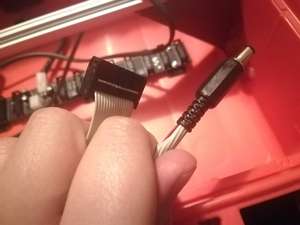
So I just soldered a barrel jack onto the 5V and ground pins of a 16 pin cable. (Remember the jack is center negative! NOT positive like in every other application)
Audio jack
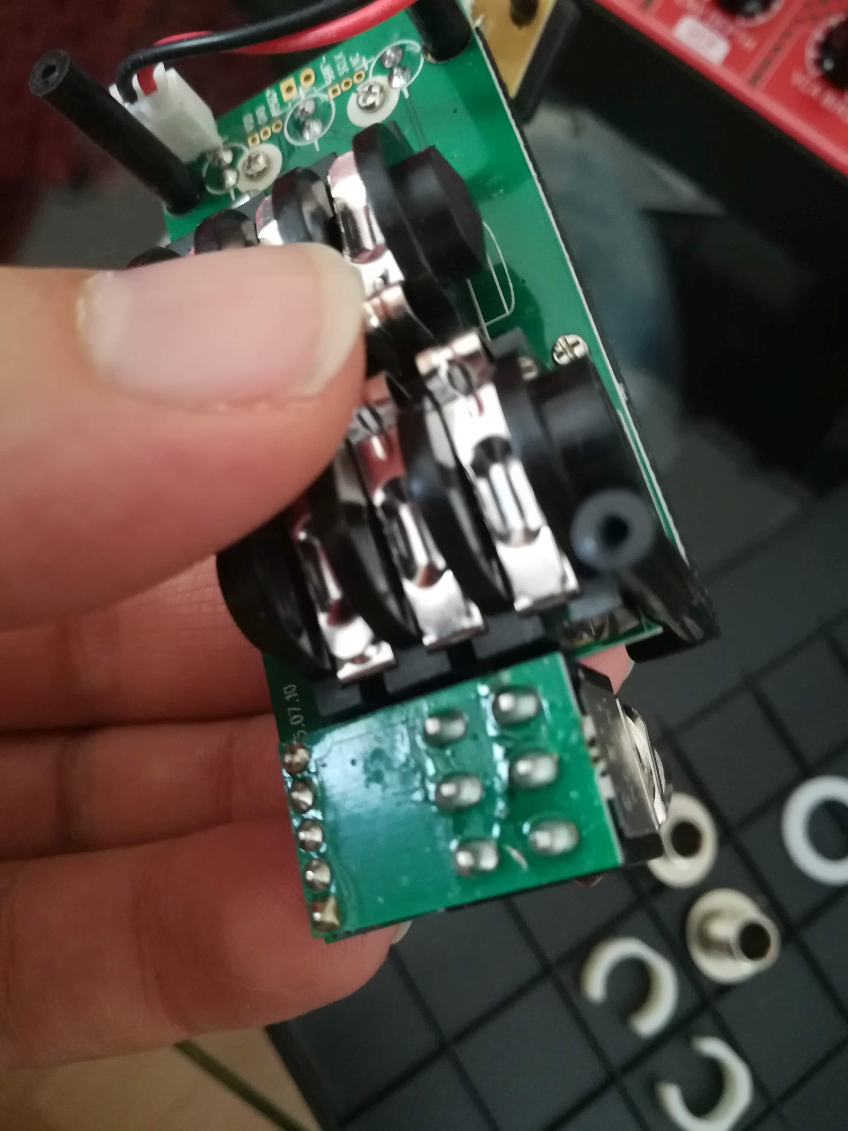
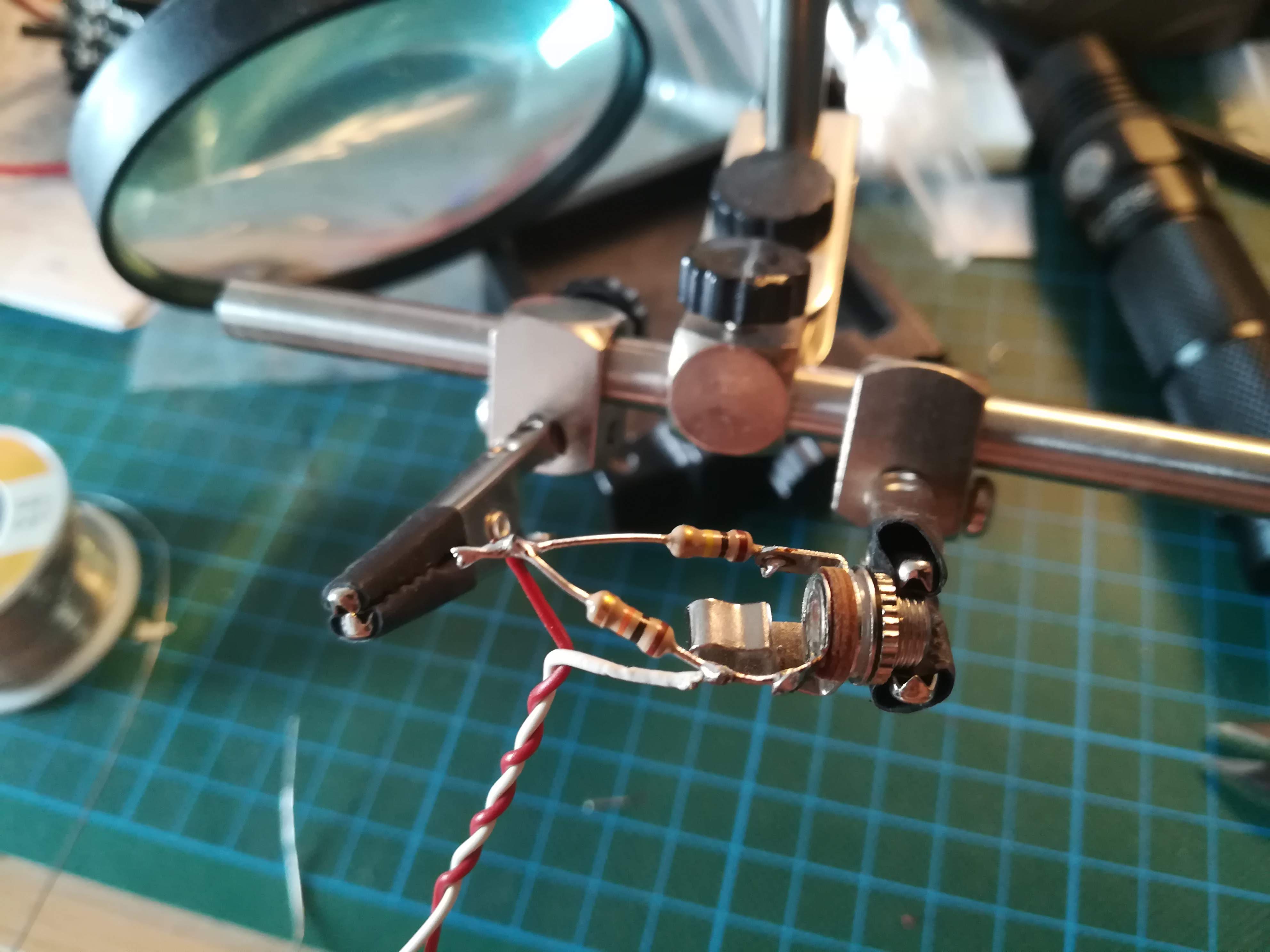
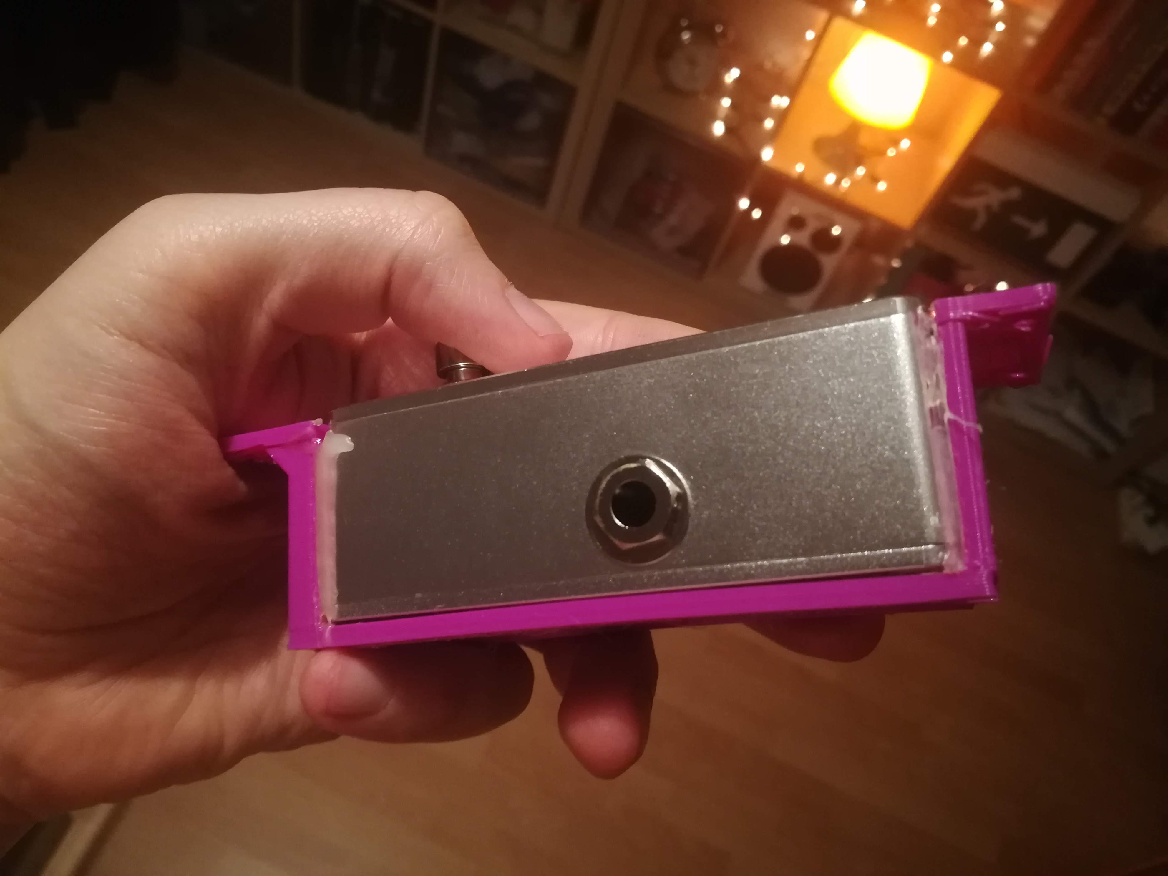
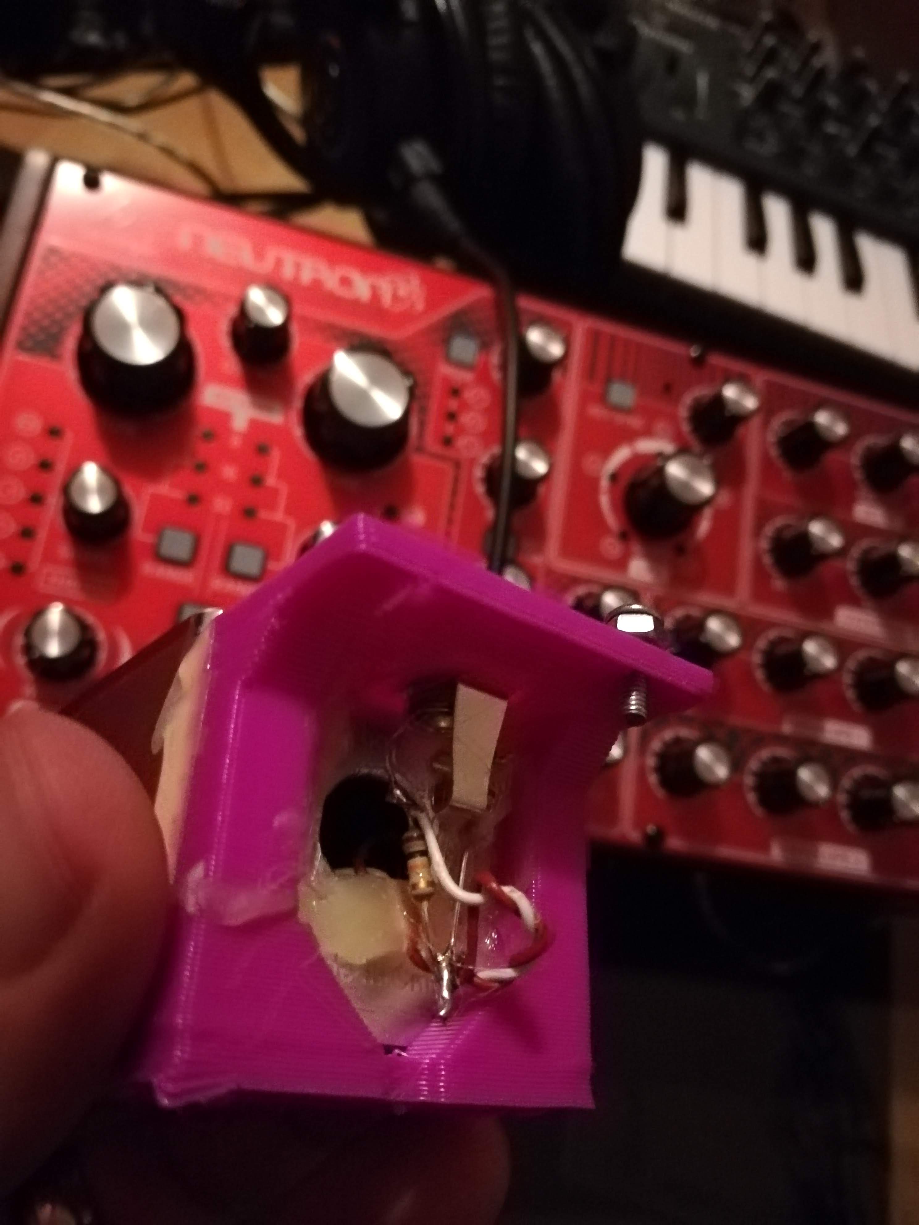
I wanted a 3.5mm audio jack on the front panel to accept the signal. The wires to the 3.5mm jack were soldered to the pins of the 6.3mm jack behind the foot switch. (polarity is marked in the picture)
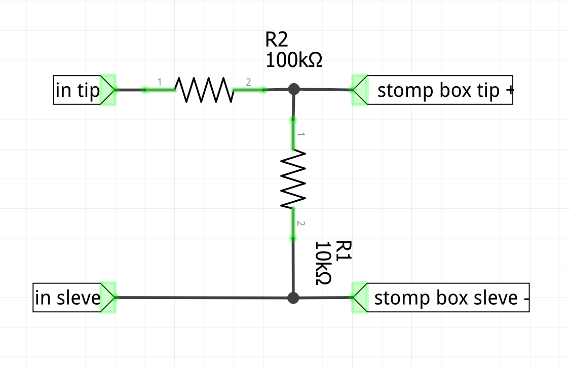
I also wanted to reduce the eurorack audio levels down to line levels with the following circuit (I have no Idea if that works like intended, but it seems so)
Testing
Electrically everything was done. I tested the tuner with my Behringer Neutron and it worked. Low noted weren't picked up and if you got to far away from a sinus wave it stopped working too. Not perfect, but good enough for my taste.
Case modifications
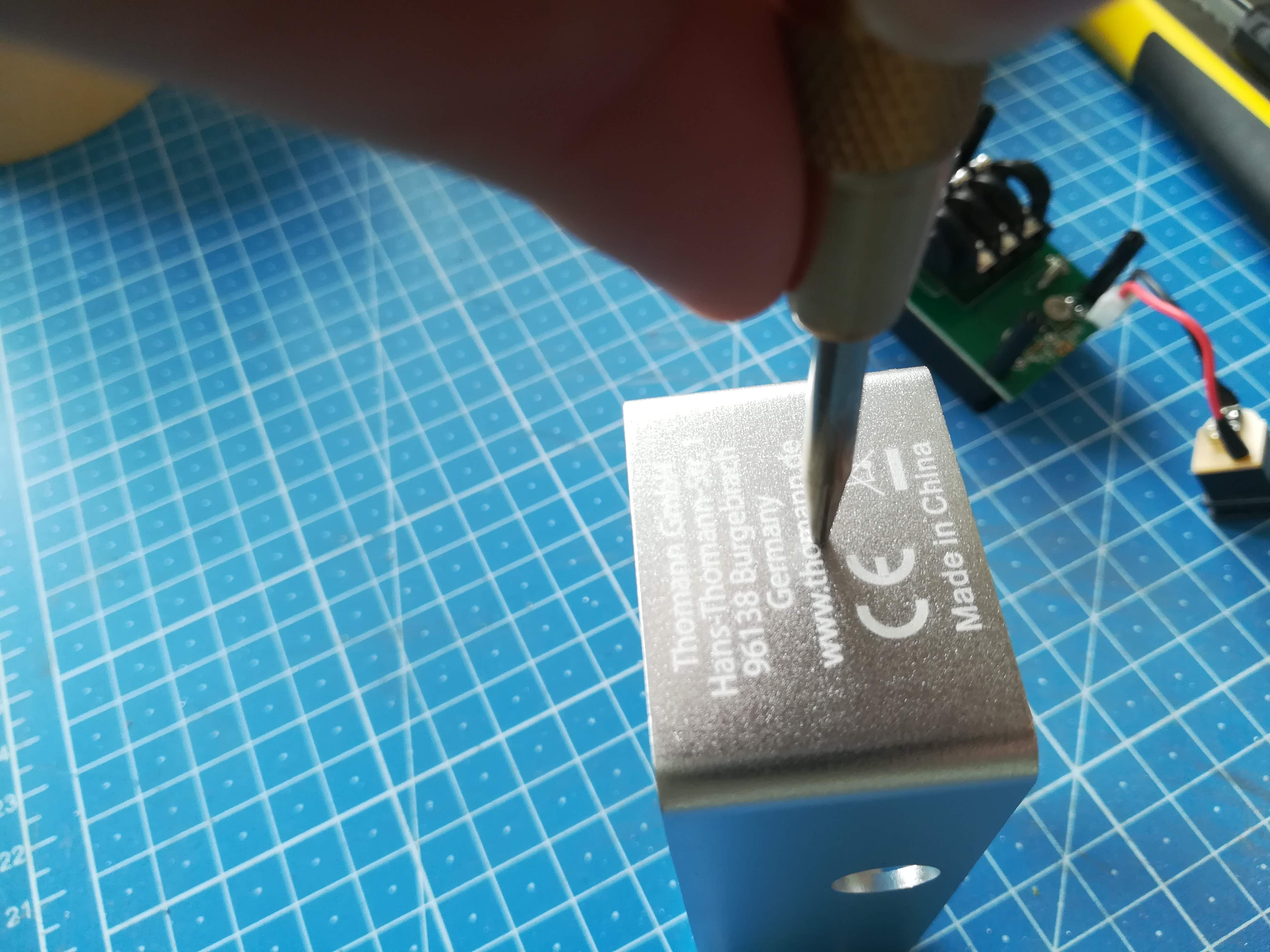
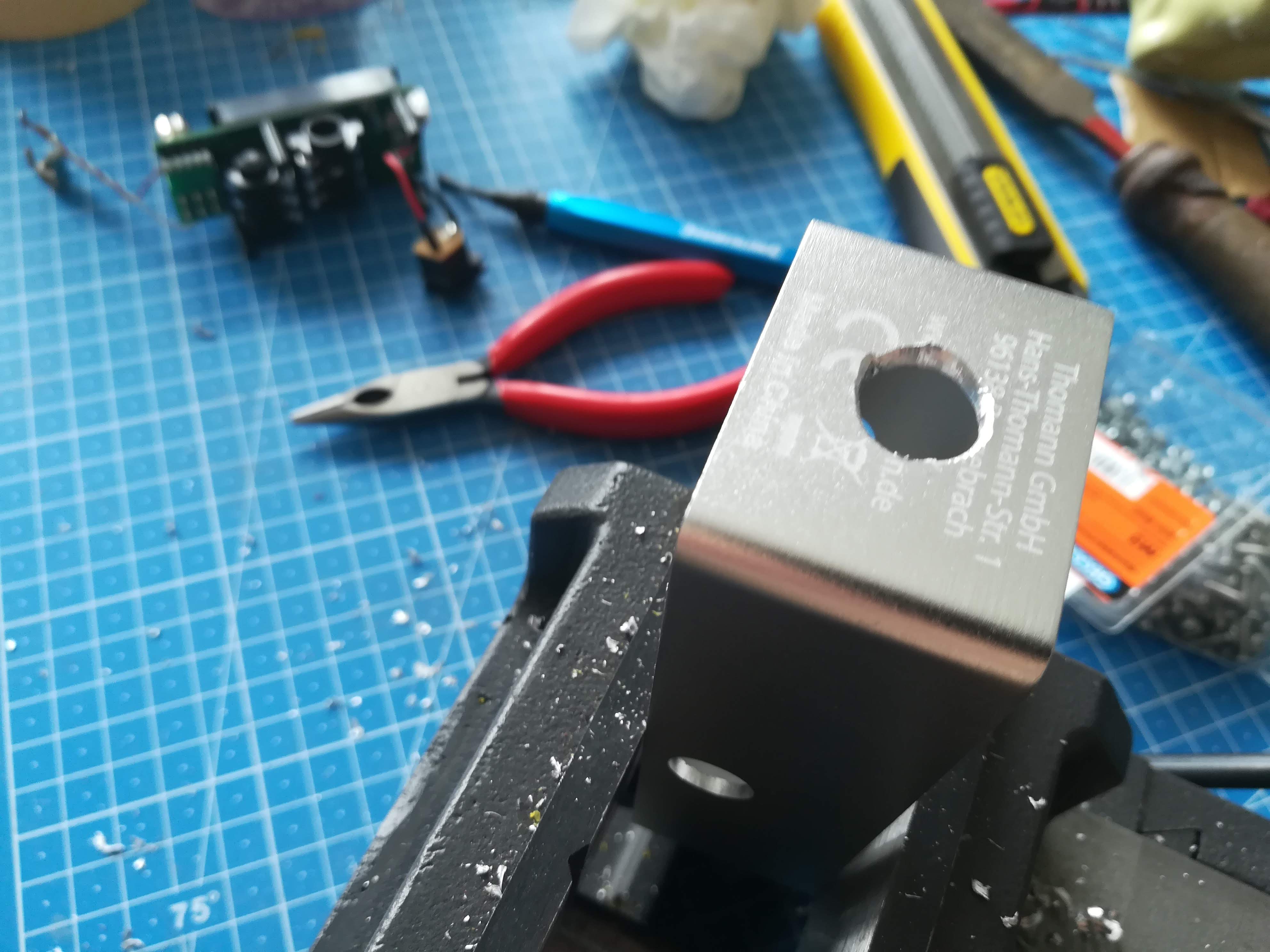
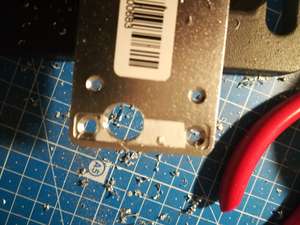
Two modifications needed to be done. First I needed a hole to get the wires and the jack out. I just center punched the right location,drilled a hole and was done.

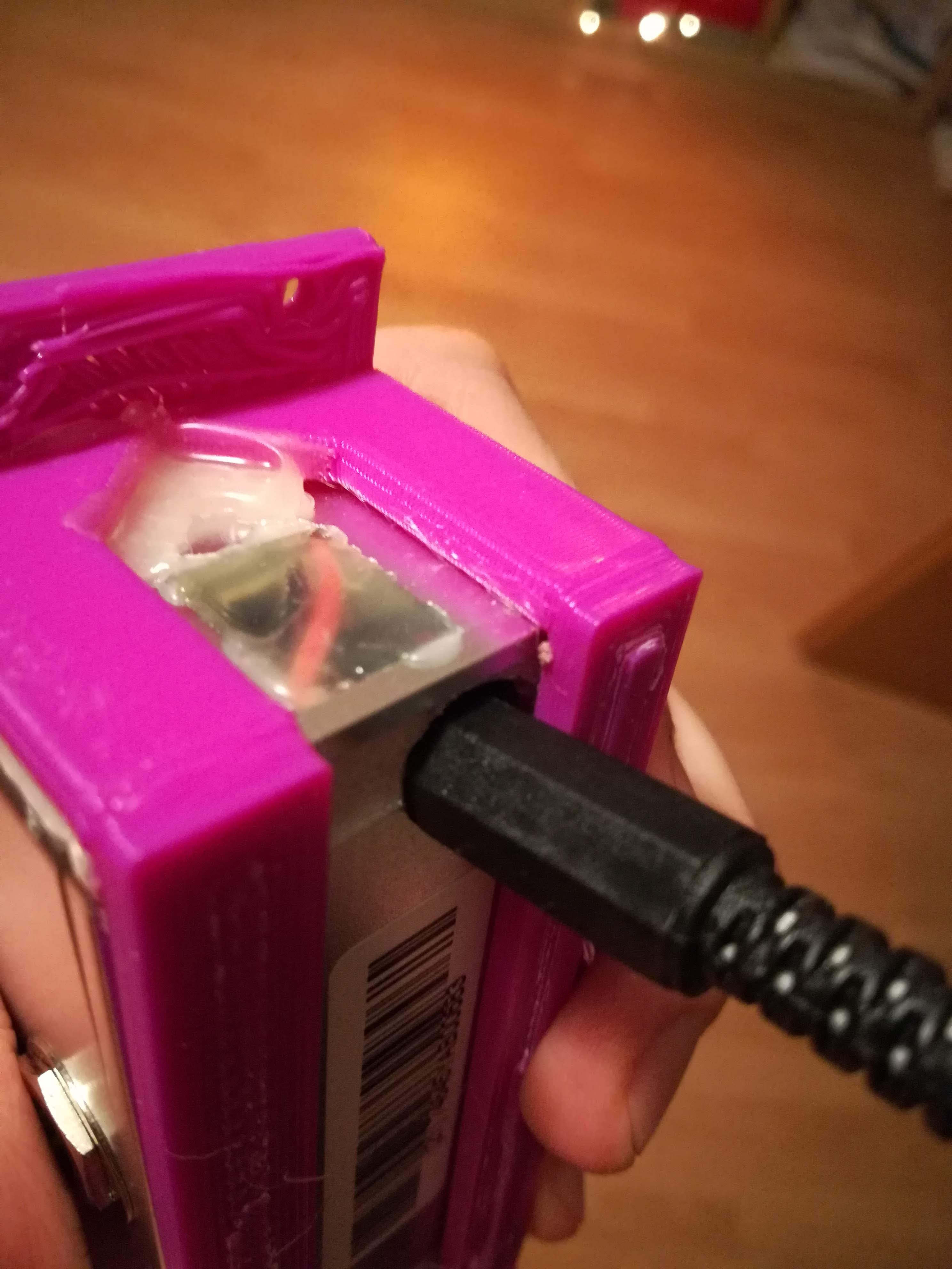
I also needed to change the Position of the power jack to fit the whole box between the rails of my modular setup. I drilled a hole in the bottom beneath the original power jack position to glue it n later.
Mounting to the rails
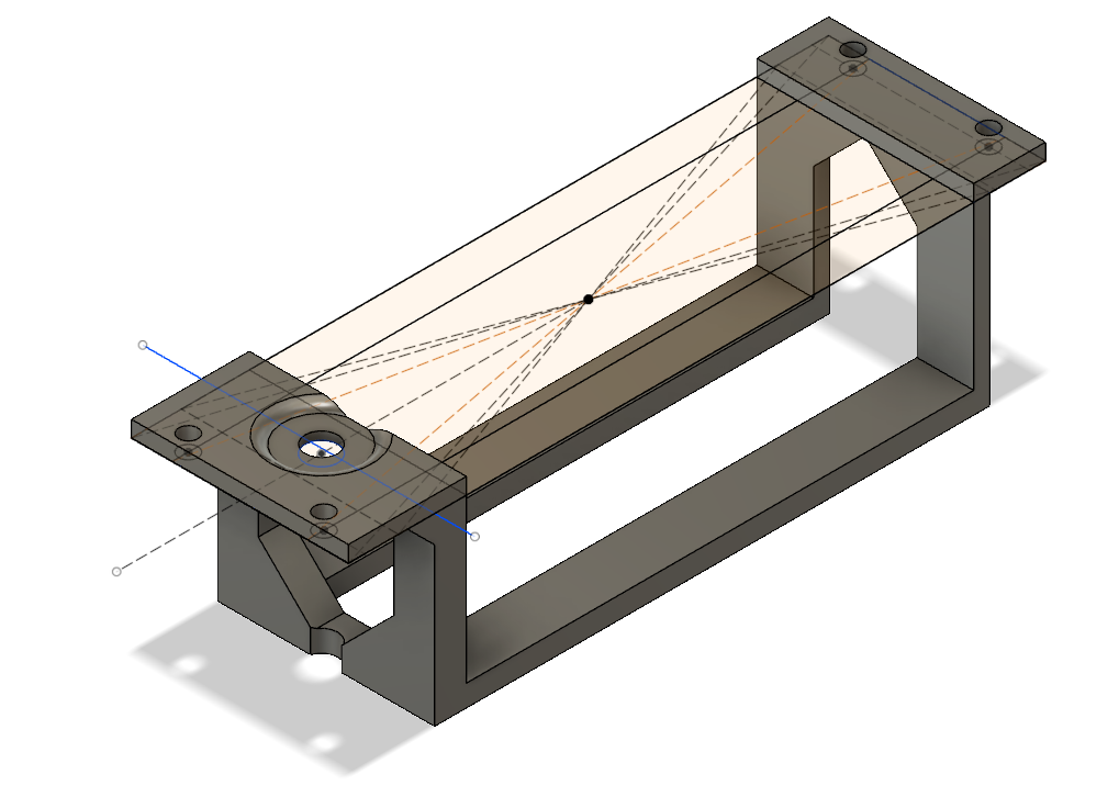
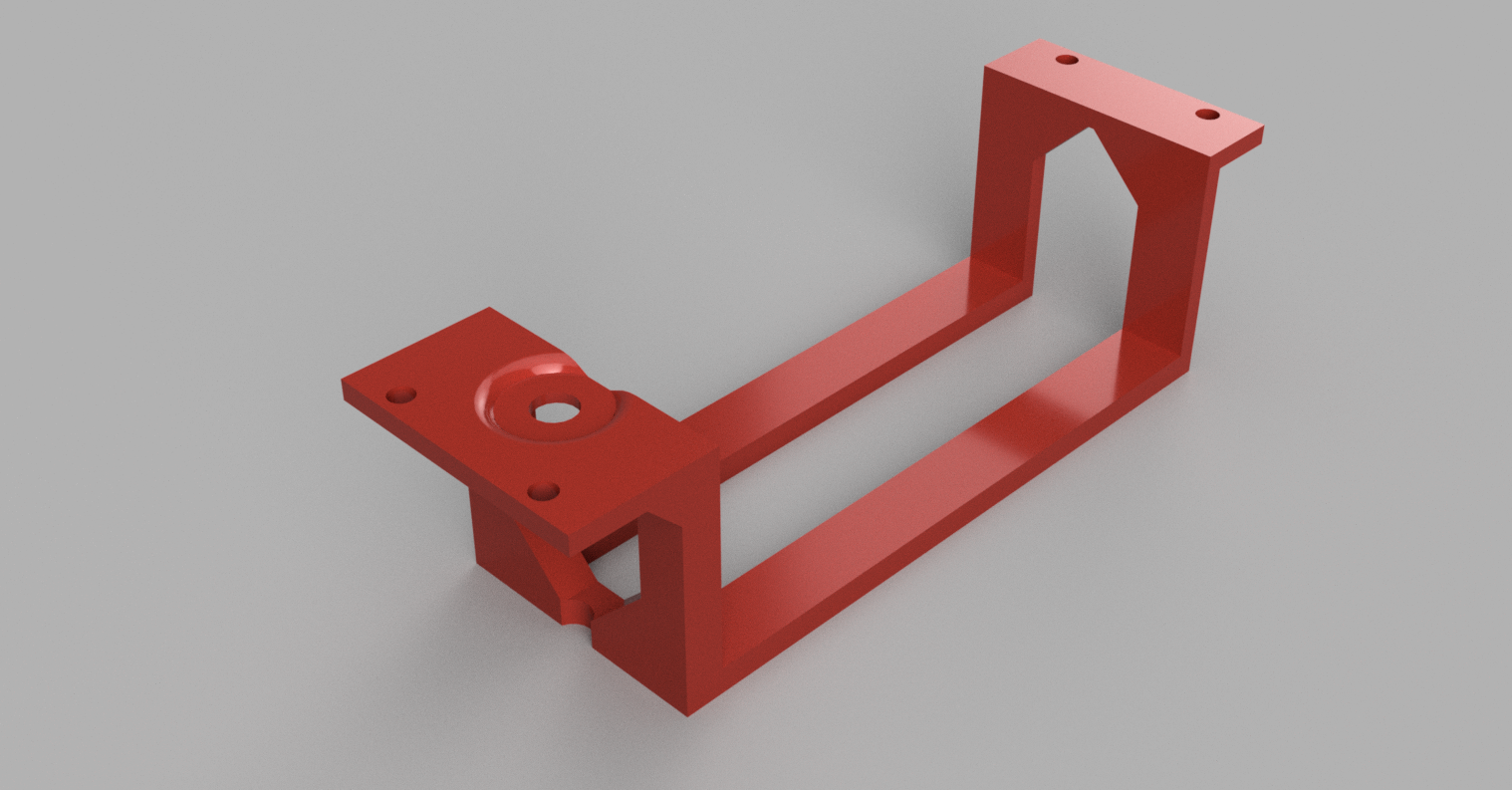
I designed a mounting in Fusion 360. It was ok, but it is relatively week due to space limitations and the odd geometry.
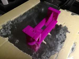
I printed the mount in PLA on a Creality CR-10 with a 0.8mm nozzle and 0.4mm layer height. Really rough but ok.
Putting everything together
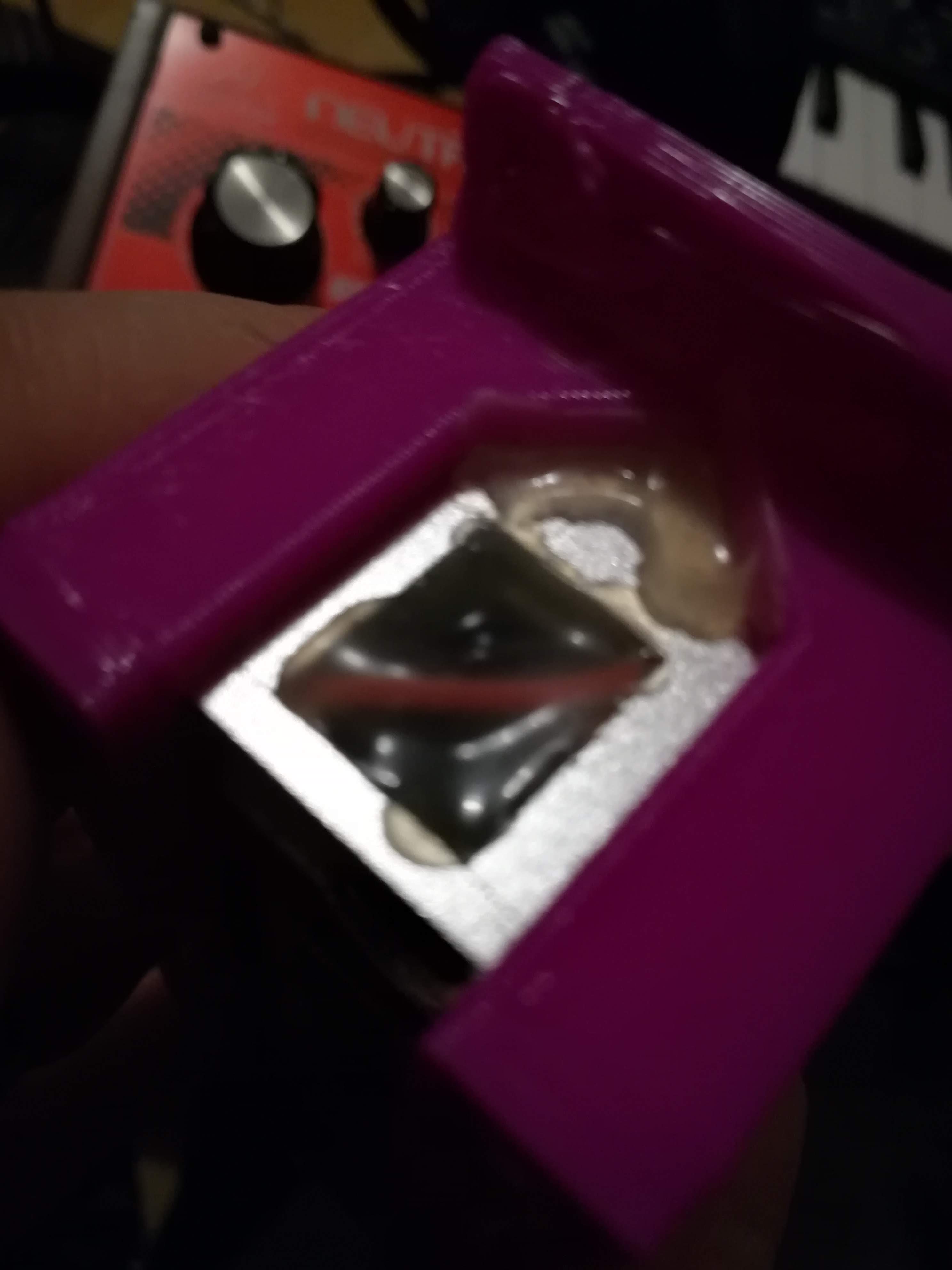
The box was glued into the plastic parts with hot glue. And mounted the audio jack.
I plugged in the power cord so the jack is correctly aligned and glued the jack into place through the original mounting hole.

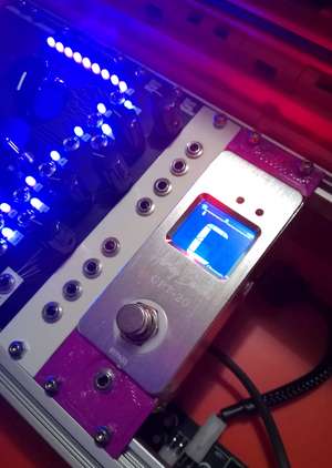
It is done
It was done and I was proud.
I just had to mount it and start everything.
No happy ending
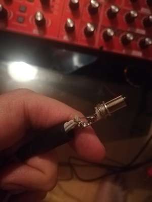
Everything seems to be ok and running but the display never or rarely changed. I looked for the error and when i moved it sometimes stopped working all together and switched of. This should have been the moment where I take a deep breath and think for a minute. But I didn't. I continued looking and poking and while i moved the module around the whole case went out and there was lots of smoke. I cut the power as fast as I could, but my custom cable was badly burned.
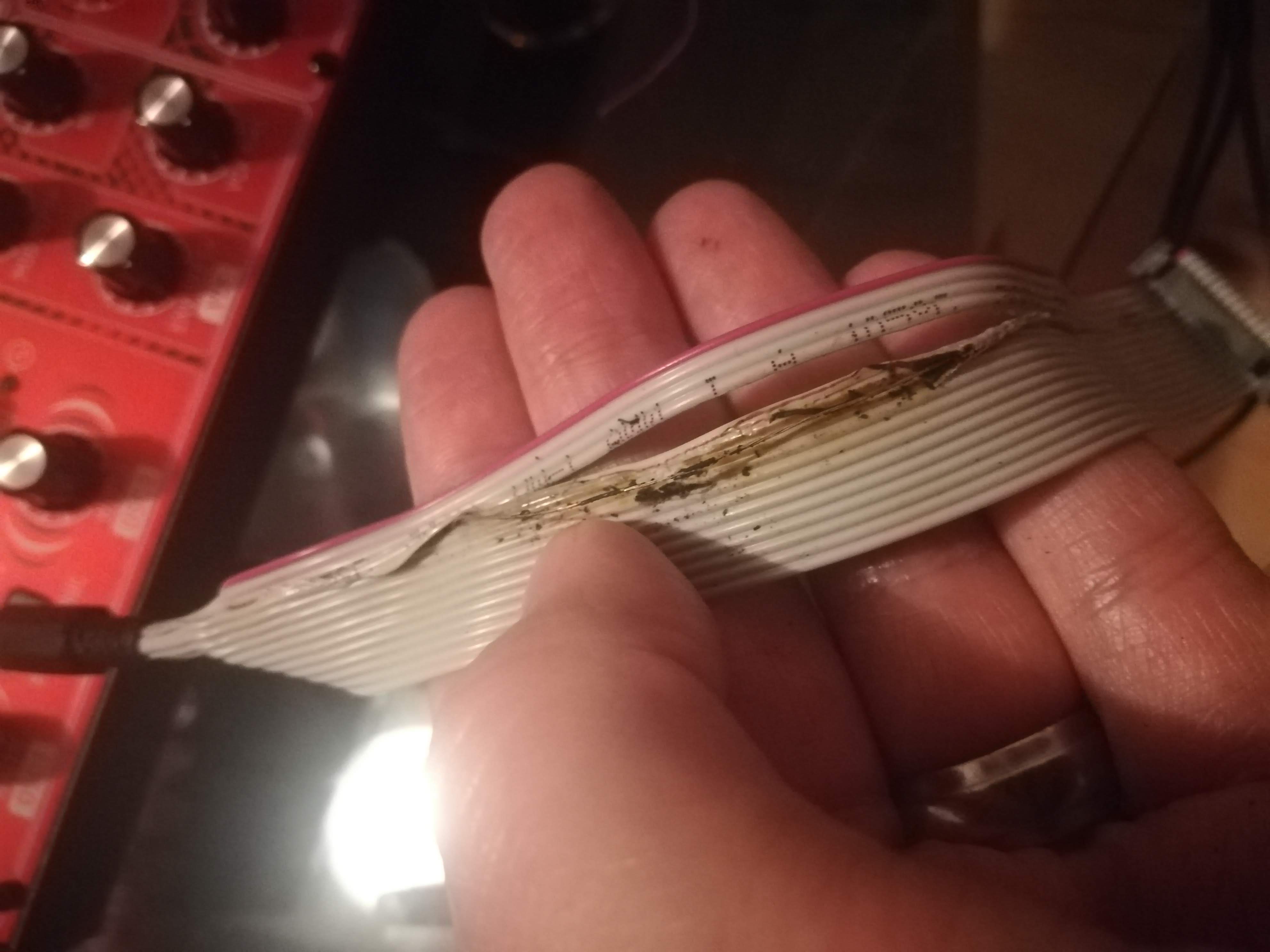
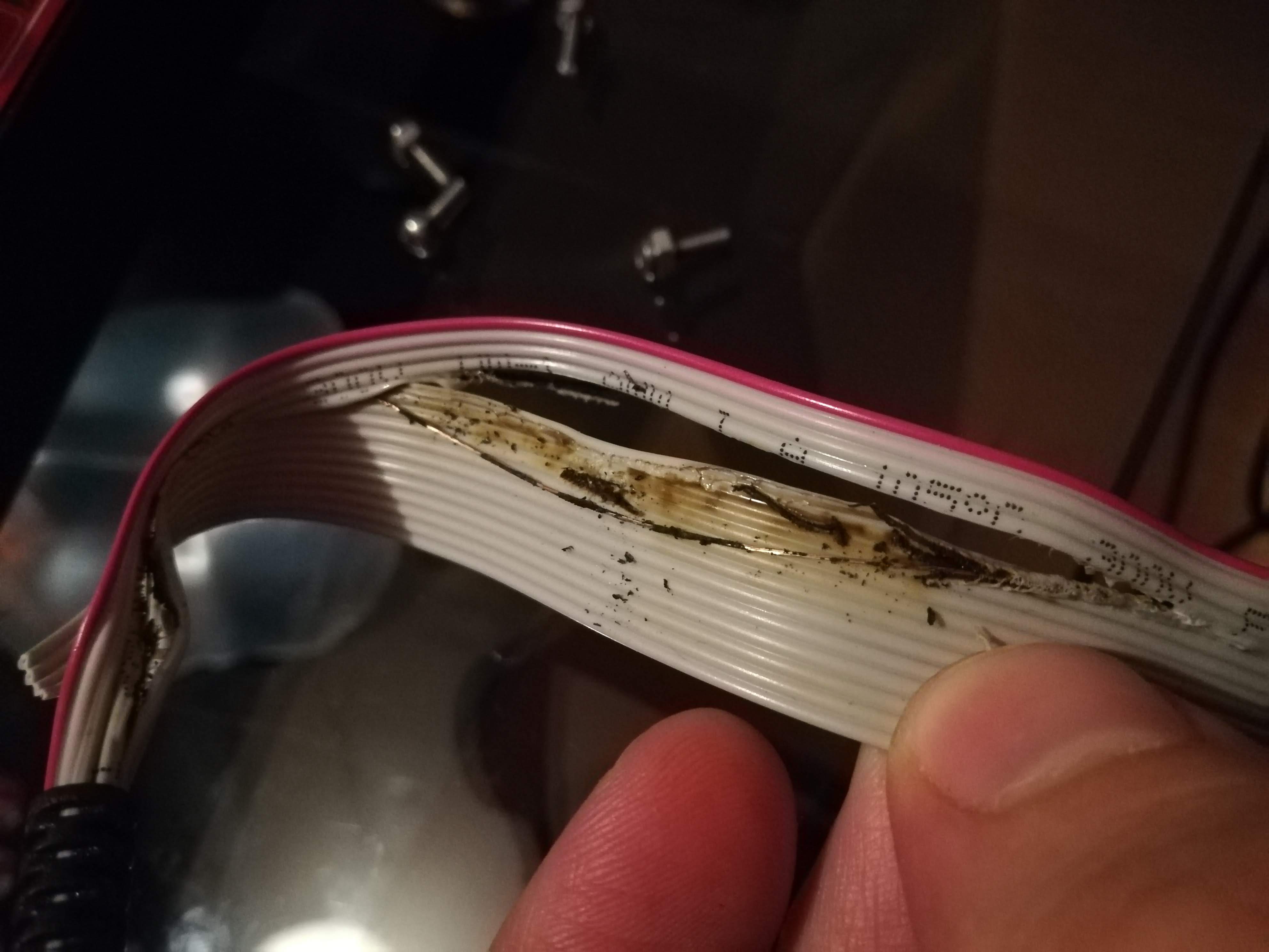
Later I found the problem. I was careless with the assembly of my power jack and had too long wires and too little insulation. That's why I got a big short and melted the cable.
After this massive fail I hab enough for today.